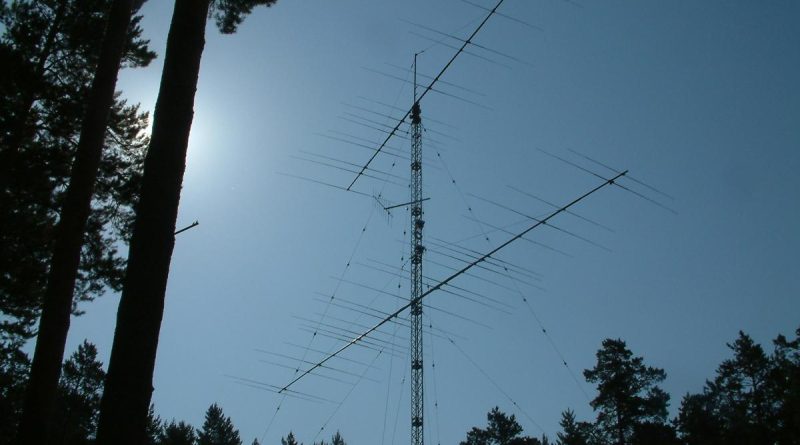
UA9BA Stacked Yagi Antennas Vladimir Umanets. From DXNews.com
UA9BA way of building stacks.
Ural Mountains are in such geographical position thatthree of the most populated areas – Europe, Asia and South-West Pacific – are in the opposite directions from UA9A,C,F,J,W. So, a high scoring effort from the Urals without illuminating these areas at the same time while running is impossible nowadays. There are few solutions to cope with the task of simultaneous illumination. One is to have two different antennas on different towers each pointed its way – either West or East. Why on different towers? Easy, if placed on the same towerwithin a few meters from each other, but beaming the opposite directions they will badly interact, so one must space the antennas at least 0,3-0,4 λ appart- a solution number two, but what a waste of tower(!). The 3rd solution is to place antennas on the same tower at the same height,even worse – on the same boom. See the picture in Fig.1 of the first such “push-pull” configuration..
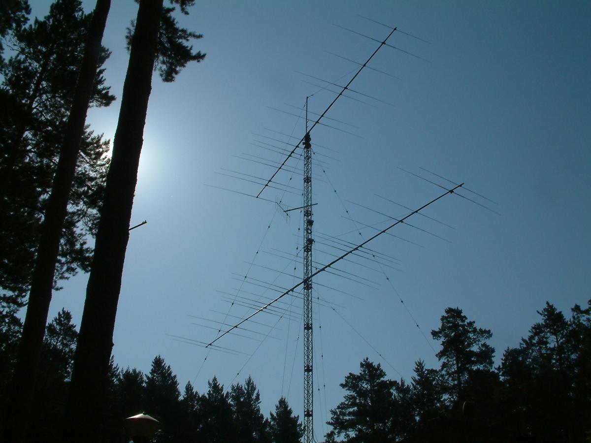
Fig.1 A two layer 15/10m stack at UA9CLB’s (now R9DX) built in Aug. of 2005.
The two bottom 15m antennas sharing the same boom and reflector don’t see each other at all, or better say almost don’t see each other – for some reason they unexpectedly enhance each other’s F/B performance! Many such bidirectional antennas on all HF (40m through 10m) bands were built in the areasince 2005.As one of the recent examples see in Fig.2 picture of the antenna farm of RM9A with 3-layer stacks on 20 through 10 meter bands and a 2-layer one on 40 meters all using bidirectional fixed antennas.
I will reveal some detailed information on how we feed such antennas in this article. We’ll consider the 3 layer stack on 15m band which is being under construction at Damir’s big station RK9AX.
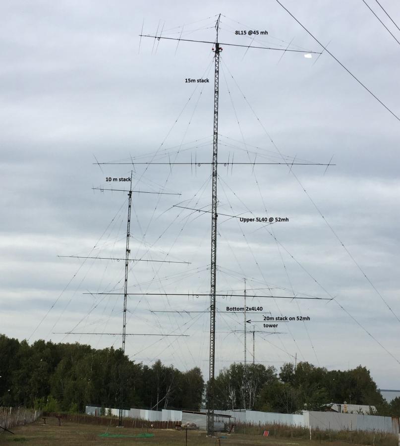
Fig2.
2.Description of the antenna and requirements
The schematics of the antenna are shown in Fig.3.
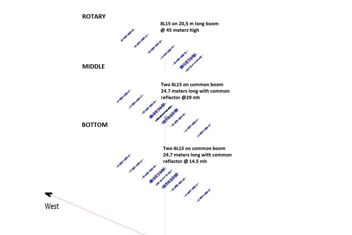
Fig 3
The antennas are fed by means of UAPD method ( For more details see my article at https://dxnews.com/ua9ba-stacking-yagi-part-1/). UAPD means Uneven Amplitude & Phase Distribution between the layers of the stacked antennas, which helps fill the nulls in the H-plane pattern of the stack at angles above the first main lobe. This unevenness requires a more complicated feeding, of course. But not only that. Here in the Urals as in any other place on Earth band conditions on 15 meters come first from the East and move towards West with the sun. Here in Russia we are limited to 1 kW output and wasting this modest amount of RF energy in the directions that are unlikely to produce QSOs isn’t wise. So, not only uneven distribution between the layers of the stack is required, but also between eastern and western fixed antennas. The ratio between RF power to East and West should change with the day progressing: most or all of available RF power to the east at early hours and little to the West, with European signals starting to come in one should start illuminating western hemisphere more and by the end of the day (end of band conditions for us at 56 degrees North) there’s no reason to illuminate the eastern hemisphere, but point all RF power to the West. In our case we’ll accept the following combinations of RF power splitting between eastern and western bottom two(“Middle” + “Bottom”)antennas:
1. 25% to western antennas, 75% to eastern antennas;
2. 25% to eastern antennas, 75% to western antennas;
3. 50%/50%;
4. 100% to eastern antennas, 0% to western antennas;
5. 100% to western antennas, 0% to eastern antennas;
Besides, the switch box shall provide the following combinations of RF power between the layers of antenna:
1. 100% to “Rotary” and non to neither bottom two;
2. 100% to western antennas(66.6% to “Middle” and 33.3% to “Bottom”) or 100% to eastern antennas (66.6% to “Middle” and 33.3% to “Bottom”), non to “Rotary”;
3. 50% to “Rotary”, 33.3% to “Middle” and 16.6% to “Bottom”;
Switch box shall also provide correct phasing of all antennas. For this particular case of RK9AX 3-layer 15 meter stack I’ve chosen the following phasing: the “Rotary” is fed with 0⁰ degrees delayed signal, the western “Middle” is fed with 145⁰ degrees delay, the western “Bottom” is fed with 120 degrees delay, eastern “Middle” is fed with 120⁰ phase delay and eastern “Bottom” is fed with 95⁰ degrees delay. The 25 degrees difference between western and eastern delays is because of 1 meter shift of the booms of fixed antennas towards West (to let the reflector out of the tower).See the patterns for “All three” and “Bottom two” layers in Fig.4.
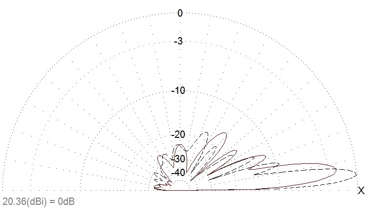
Fig. 4
The H-plane pattern for all three antennas aligned in western direction with powers and delays 50%(0⁰), 66.6%(145⁰) and 33.3%(120⁰) is represented by dashed line. It shows 20.36 dBi of Gain at an elevation angle of 5.4 degrees. The solid line represents the “bottom two” alone with maximum Gain of 18.31 dBi at 7.6 degrees. What’s important is how smoothly the two combinations fill the first 25 degrees. There are no deep gaps in combined pattern.
Now look in Fig. 5at the same pattern of the same antenna (“All three”, “Bottom two”), but fed by classic way, i.e. all antennas get equal amount of power, all antennas are fed in phase. In our case, though, “in phase” means 0° to the “Rotary”, 118° lag to the “Middle” western and 118° lag to the “Bottom” western. These phase lags compensate the geometrical shift of feed point positions of antennas on different layers – the feed point of the “Rotary” is shifted backwards from the feed points of the bottom two antennas by 9.45 meters which equals 242° lag in the air.
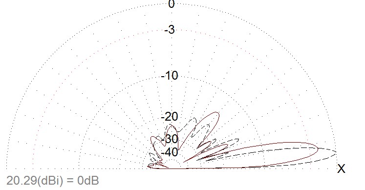
Fig5
The dashed line shows the pattern of “All three” and solid line is the response of the “Bottom two”. The Gain of all three is 20.29 dBi which is slightly less than that of UAPD fed stack in Fig.4, and the maximum Gain occurs at a slightly higher angle of 5.6 degrees, whilst the Gain of the bottom two is 7.9 dBi which is higher than that of the UAPD feeding. I did so on purpose – I wanted a wider coverage (smoother fills at higher angles) in the H-plane of the “Bottom two” with UAPD feed shown in Fig.4 at the cost of a small fraction of a dB. Now, please note,dramatic difference between the combined fills of low angles by the same antenna but fed by two different ways. When fed by UAPD method the -10dB fill is 16 degrees high (wide) and -14 dB level is 26 degrees high(wide), whilst those for the classic method of feed are for -10 dBi – 14.5 degrees and that’s the end of story. No significant high angle fills above 14.5 degrees!
3. The schematics of the switch box
As you see in Fig. 6the power splitting and phase delays are done by means of coaxial line transformers and coaxial lines. All switches are Russian made vacuum relays rated at 15A, 3kV. The status of relay contacts (“+” if shorted, empty field if open) for different combinations of power distribution to the antennas is listed in the Table 1.
TABLE 1
Number of Switch | 1 | 2 | 3 | 4 | 5 | 6 | 7 | 8 | 9 | 10 | 11 | 12 | 13 | 14 |
All antennas connected.Power distribution:Rotary 50%, Western two 37.5%, Eastern two 12.5% | + | + | + | + | + | + | ||||||||
All antennas connected.Power distribution:Rotary 50%, Western two 12.5%, Eastern two 37.5% | + | + | + | + | + | + | ||||||||
All antennas connected. Power dstrbtion:Rotary 50%, Western two 25%, Eastern two 25% | + | + | + | + | + | + | ||||||||
Rotary and Western two connected. Power distribution: Rotary 50%, Western two 50% | + | + | + | + | + | |||||||||
Rotary and Eastern two connected. Power distribution: Rotary 50%, Eastern two 50% | + | + | + | + | + | |||||||||
Rotary alone 100% of Power | + | |||||||||||||
Western two 100% of Power | + | + | ||||||||||||
Eastern two 100% of Power | + | + |
A few words about the schematic diagram of the Switch Box in Fig. 6. All transformers and switches are mounted in an aluminum box Capacitors C1, C2, C3 and C4 tune out the inductive reactance of wiring (relay’s inner conductors, wires between the relays, wires
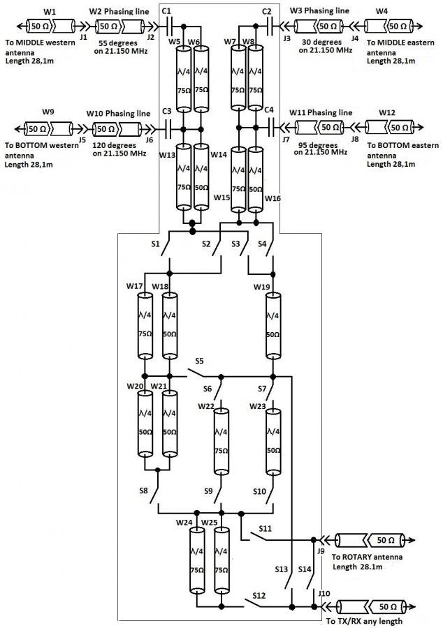
Fig.6
from relays to coaxial line transformers and so on) inside the switch box.One MUST tune out the inductive reactance of the wiring, otherwise it will affect the correct phasing of the antennas! The tuning process is very simple – turn on the “All antennas connected, 50% Rotary, 25% west, 25% East” combination, load “TX/RX” J10 Jack with 50 Ohm load, also load J3, J7, J6 and J9 with 50 Ohm dummies, connect the VSWR meter to J2 and start tuning C1 for minimum VSWR. Similar procedure applies to C2, C3 and C4. The shorter are the wires inside the box the bigger are the volumes of the capacitors. Recommended way of arranging 4 coaxial line junction is shown in Fig.7.The braid plate should be firmly mounted on ground chassis of the box.
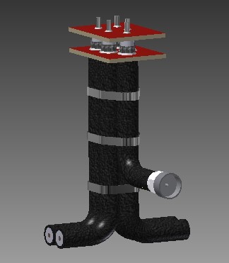
Fig7. An example of 5 coaxial line junction arrangements.
One might say, that this Willy-bo must be nuts with such complicated way of feeding vertical stacks. Well, may be. I’ve first implemented this way at UA9AYA club station in 1999, and never since I thought it was too much trouble because the outcome was always worth the efforts. And o’cose!There’s a simpler way even with UAPD in place. Look for one in Fig.8, for example. This Box allows the following combinations:
1. Rotary 50%, West 25% and East 25% (S1, S2, S4, S3 shorted) VSWR 1.1:1
2. West 100% (S4, S1 shorted) VSWR 1.1:1
3. East 100% (S4, S2 shorted) VSWR 1.1:1
4. Rotary 100% (S3 shorted) VSWR 2:1- can only be used for RX!
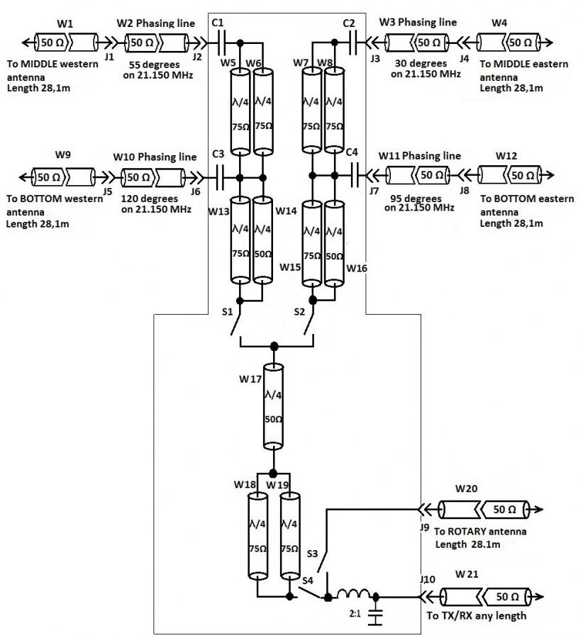
Fig8. Simple Switch Box with UAPD in place
A more sophisticated unit is shown in Fig.9. This one can do more and better than the one in Fig. 8. It does all the combinations the simpler one in Fig. 8 does, besides it connects the Rotary alone with VSWR 1:1 through switch S8 contacts shorted. Plus two more combinations: it can do Rotary 50% and West 50% through S3, S6 and S9 with VSWR 1:1 and it can do Rotary 50% and East 50% through S3, S7 and S9.Please note, the lengths of coaxial lines W21, W23 on Fig.9 are ½ wavelength long not ¼! That takes care of correct phasing for the two last combinations.
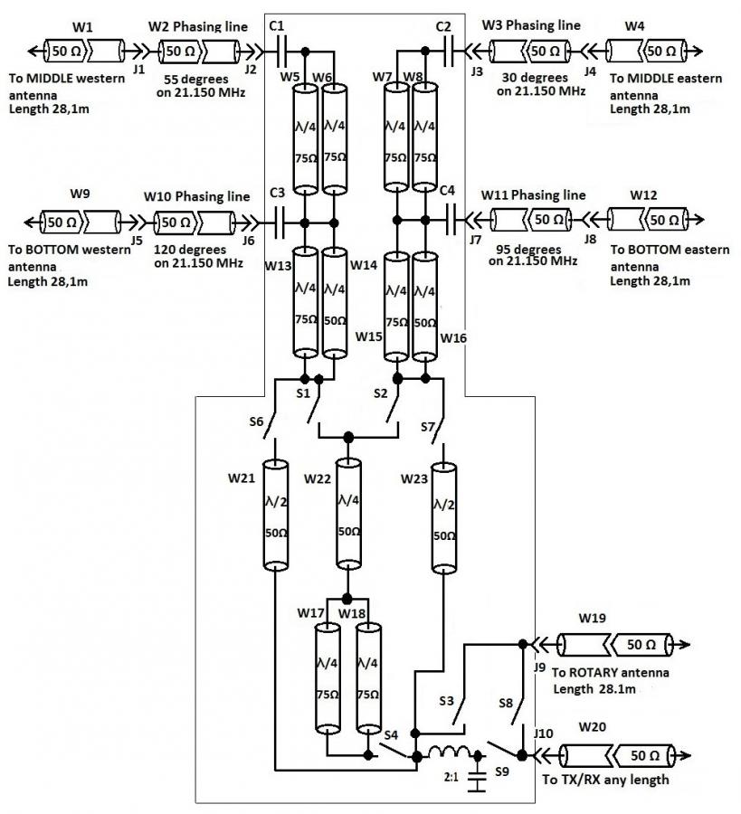 Fig9
Fig9
4. Final comments
Below are the links to the MMANA files for the UAPD and Classic ways of feed considered in this article. So, The DIY types can play around with the numbers themselves to verify my presentation of patterns. Please keep in mind that this is all over FLAT terrain. In case of mountainous type of terrain the real profile should always be taken into account, otherwise severe mistakes with UAPD can occur.
15m 3 Layer stack all three classic feed
15m 3 layer stack all three UAPD feed
15m 3 layer stack bottom two classic feed
15m 3 layer stack bottom two UAPD feed
73! GL with antennas!
Vladimir (Willy) Umanets UA9BA Karataban, 30 September 2017

sumber www.dxnews.com

